APPLICATIONS OF INTERNAL COMBUSTION
ENGINES
1.
Automotive: (i)
Car
(ii) Truck/Bus
(iii) Off-highway
2. Locomotive
3. Light Aircraft
4. Marine:
(i) Outboard
(ii)
Inboard
(iii)
Ship
5. Power Generation: (i)
Portable (Domestic)
(ii) Fixed (Peak Power)
6. Agricultural: (i)
Tractors
(ii)
Pump sets
7. Earthmoving: (i)
Dumpers
(ii)
Tippers
(iii)
Mining Equipment
8. Home Use: (i) Lawnmowers
(ii) Snow blowers
(iii) Tools
9. Others
BASIC TERMS
REGARDING ENGINES
01)Bore
The inside Diameter of
the Cylinder is known as the Bore and it is measured in millimeter (mm).
02) Stroke
It is the distance travelled
by the Piston from one of its dead centre position to the other dead centre
position.
03) Dead Centre
They corresponds to the
positions occupied by the piston at the end of its Stroke,where the centre line
of the Connecting Rod and Crank are in the same straight line.For Vertical
Engines these are known as Top Dead Centre (T.D.C) and Bottom Dead Centre
(B.D.C) position.In Horizontal Engines,these are known as Inner Dead Centre
(I.D.C) and Outer Dead Centre (O.D.C) position.
04) Top Dead Centre
In Vertical Engines,the
top most position of the Piston towards the cover end side of the cylinder is
known as Top Dead Centre.
05) Bottom Dead Centre
In Vertical Engines,the
lower position of the Piston towards the Crank end side of the cylinder is known
as Bottom Dead Centre.
06) Piston Displacement
It is also known as
"Swept Volume".It is the volume through which the Piston sweeps for
its one Stroke.It is equal to the Area of cross section of the Piston
multiplied by its Stroke Length.
07) Clearance Volume
It is the Volume included
between the Piston and the Cylinder Head when the Piston is at its Top Dead
Centre in Vertical Engines and inner Dead Centre in Horizontal Engines.The
Clearance Volume is generally expressed as percentages of Swept Volume.
08) Compression Ratio
It is the ratio of the
total Cylinder Volume to the Clearance Volume.For Petrol Engines the value of
Compression Ratio is varies from 5:1 To 9:1 and for Diesel Engines varies from
14:1 To 22:1
09) Piston Speed
It is the distance
travelled by the Piston in one minute.The piston Speed=2LN meter/min.If the
R.P.M. of Engine Shaft=N and length of Stroke=L meter.
10) Crank Throw
This is the distance
between the Centre of Crankshaft and Centre of Crank Pin.The distance will be equal
to half the Stroke Length
11) Carburetion
The process of breaking
up the fuel into minute particles and mixing it with air is called
"Carburetion". This process is mostly used in the internal combustion
engine, which have low compression ratio and which use highly volatile liquid
fuels such as petrol. The process of breaking up fuel in minute particles is
known as "Atomization". Carburettor is the device where all the
carburetion takes place.
12) Scavenging
The process of removing
burnt exhaust gases from the combustion chamber of the engine cylinder is known
as "Scavenging". In four-stroke cycle engine, the piston pushes the
burnt gases to exhaust manifold during its exhaust stroke. In the two-stroke
cycle engine a blast of fresh charge is made to enter at higher velocity into a
combustion chamber at the end of working stroke and thus drives out burnt
exhaust gases.
13) Compensation
The process of providing
additional fuel or reducing the fuel by certain means to correct the mixture
strength to meet the varying nature of speeds and load on the engines is known
as "Compensation". This process is mostly used in simple carburettor
specially used for automotive purposes.
14) Firing Order
The sequences in which
firing or power impulses occur in an internal combustion engine are called
"Firing Order". The firing order should be such that there is always
a proper balance and it does not cause vibrations.
15) Detonation
Some sudden and violent
knocks are experienced in internal combustion engine at sometimes. This knocks
are known by "Detonation". This knock is set up by a high pressure
wave giving a loud pulsating noise as it strikes against the cylinder walls,
cylinder head and piston. It should be noted that detonation is not pre-ignition
but something, which occur after the spark, has started the ignition.
16) Doping
The process of adding
small quantity of Tetraethyl lead to suppressed the detonation in petrol engine
is called "Doping". If the tetraethyl lead used in large proportion,
there are chances of engine damage due to deposition of lead oxide in the
combustion chamber.
17) Diesel Knock
A high pressure wave set
up in compression ignition engine (Diesel Engine), which causes knocks. This
knock is called as "Diesel knock". It badly affects the engine
efficiency and power drop; also engine runs very rough due to diesel knock.
18) Dissociation
If a gas or mixture of
gases is heated to very high temperature, the vibrating molecules of different
gases make violent encounters resulting in splitting up of the compound
molecules into smaller molecules which recombine to form their compound
molecules as the temperature lowered. The phenomenon is called
"Dissociation". The dissociation is mainly due to breaking up of
carbon dioxide into carbon monoxide and oxygen.
19) Supercharging
The process of increasing
the weight or density of air-fuel mixture or compressed air, induced into the
cylinder during the induction stroke is known as "Supercharging".
This is achieved by a separate compressor and known as supercharger or blower.
20) Turbulence
When the atomised fuel
injected into the combustion chamber of compression ignition engine may be
burnt efficiently there should be a high relative velocity between the air and
fuel so that a thorough mixing takes place. This is achieved by
"Turbulence".
GENERAL
VIEW OF AN ENGINE

CLASSIFICATION
OF INTERNAL COMBUSTION ENGINES

-Based on motion, no. of cylinders &
arrangement
1. Reciprocating: (a)
Single Cylinder
(b) Multi-cylinder (I) In-line
(ii) V
(iii) Radial
(iv) Opposed Cylinder
(v) Opposed Piston
2. Rotary: (a) Single Rotor
(b)
Multi-rotor
- Based on no. Of strokes per cycle
1.Four
Stroke Cycle: (a)
Naturally Aspirated
(b)Supercharged/Turbocharged
2.Two
Stroke Cycle:
(a) Crankcase Scavenged
(b) Uniflow Scavenged
(i)
Inlet valve/Exhaust Port
(ii)
Inlet Port/Exhaust Valve
(iii) Inlet and Exhaust Valve
- Based on Operating Cycle
1) Otto (For the Conventional SI Engine)
2) Diesel (For the Ideal Diesel Engine)
3)
Dual (For
the Actual Diesel Engine)
- Based on cooling
1) Water cooled engines
2) Air cooled engines
- Based on type of ignition
1) Spark ignition engine
2) Compression ignition engine
-Based on fuel used
1)
Petrol
engines
2)
Diesel
engines
3)
Gas
engines
CLASSIFICATION IN DETAIL
-Based on motion, no. of cylinders & arrangement
1. Reciprocating: (a)
Single Cylinder
(b) Multi-cylinder (I) In-line
(ii) V
(iii) Radial
(iv) Opposed Cylinder
(v) Opposed Piston
2. Rotary: (a) Single Rotor
(b)
Multi-rotor
- Reciprocating Engines
A
reciprocating engine, also often
known as a piston engine, is a heat engine that uses one or more reciprocating pistons to convert pressure into a rotating motion. There may be one or more pistons. Each piston is
inside a cylinder, into which a gas is
introduced, either already hot and under pressure (steam engine), or heated inside the cylinder either by ignition of a fuel air mixture (internal combustion
engine)
or by contact with a hot heat exchanger in the cylinder .The hot gases expand,
pushing the piston to the bottom of the cylinder. The piston is returned to the
cylinder top (Top Dead Centre) either by a flywheel or the power from other pistons connected to the
same shaft. In most types the expanded or "exhausted" gases are removed from the cylinder by
this stroke. The exception is the Stirling engine, which repeatedly heats and cools the same
sealed quantity of gas.

In all types, the linear movement of the piston is converted to a rotating movement via a connecting rod and a crankshaft or by a swash plate. A flywheel is often used to ensure smooth rotation. The more cylinders a reciprocating engine has, generally, the more vibration-free (smoothly) it can operate. The power of a reciprocating engine is proportional to the volume of the combined pistons' displacement.
A seal needs to be made between the sliding piston and the walls of the cylinder so that the high pressure gas above the piston does not leak past it and reduce the efficiency of the engine. This seal is provided by one or more piston rings. These are rings made of a hard metal which are sprung into a circular groove in the piston head. The rings fit tightly in the groove and press against the cylinder wall to form a seal.
The bore/stroke ratio is the ratio of the diameter of the piston, or "bore", to the length of travel within the cylinder, or "stroke". If this is around 1 the engine is said to be "square", if it is greater than 1, i.e. the bore is larger than the stroke; it is "over square". If it is less than 1, i.e. the stroke is larger than the bore; it is "under square".

- ROTARY
ENGINES
The rotary engine was an early type of internal-combustion engine, usually designed with an odd number of cylinders per row in
a radial
configuration, in
which the crankshaft remained stationary and the entire cylinder block rotated around it. Its main
application was in aviation, although it also saw use in a few early motorcycles and cars.

(a) Single Rotor
(b) Multi-rotor
Wankel
Engine Parts
The central drive shaft, called the eccentric shaft or E-shaft, passes through the center of the rotor and is supported by fixed bearings. The rotors ride on eccentrics (analogous to cranks) integral with the eccentric shaft (analogous to a crankshaft). The rotors both rotate around the eccentrics and make orbital revolutions around the eccentric shaft. Seals at the corners of the rotor seal against the periphery of the housing, dividing it into three moving combustion chambers. The rotation of each rotor on its own axis is caused and controlled by a pair of synchronizing gears. A fixed gear mounted on one side of the rotor housing engages a ring gear attached to the rotor and ensures the rotor moves exactly 1/3 turn for each turn of the eccentric shaft. The power output of the engine is not transmitted through the synchronizing gears. The force of gas pressure on the rotor (to a first approximation) goes directly to the center of the eccentric, part of the output shaft.

-Based on no. Of strokes per cycle
1.Four
Stroke Cycle: (a)
Naturally Aspirated
(b)Supercharged/Turbocharged
2.Two
Stroke Cycle:
(a) Crankcase Scavenged
(b) Uniflow Scavenged
(i)
Inlet valve/Exhaust Port
(ii)
Inlet Port/Exhaust Valve
(iii) Inlet and Exhaust Valve
-Four
Stroke & Two stroke
Today, internal
combustion engines
in cars, trucks, motorcycles, aircraft, construction machinery and many others, most commonly use a
four-stroke cycle. The four
strokes refer to intake, compression, combustion (power), and exhaust strokes
that occur during two crankshaft rotations per working cycle of the gasoline engine and diesel engine.
The cycle begins at Top Dead Center (TDC), when
the piston is farthest away from the axis of the crankshaft. A stroke refers to the full travel of the piston from Top Dead
Center (TDC) to Bottom Dead Center (BDC). (See Dead centre.)1. INTAKE stroke: On the intake or induction stroke of the piston, the piston descends from the top of the cylinder to the bottom of the cylinder, reducing the pressure inside the cylinder. A mixture of fuel and air is forced by atmospheric (or greater) pressure into the cylinder through the intake port. The intake valve(s) then close.
2. COMPRESSION stroke: With both intake and exhaust valves closed, the piston returns to the top of the cylinder compressing the fuel-air mixture. This is known as the compression stroke.
3. POWER stroke.: While the piston is close to Top Dead Center, the compressed air–fuel mixture is ignited, usually by a spark plug (for a gasoline or Otto cycle engine) or by the heat and pressure of compression (for a diesel cycle or compression ignition engine). The resulting massive pressure from the combustion of the compressed fuel-air mixture drives the piston back down toward bottom dead center with tremendous force. This is known as the power stroke, which is the main source of the engine's torque and power.
4. EXHAUST stroke.: During the exhaust stroke, the piston once again returns to top dead center while the exhaust valve is open. This action evacuates the products of combustion from the cylinder by pushing the spent fuel-air mixture through the exhaust valve(s).

Two-stroke
Engine

A
two-stroke engine is an internal combustion engine that completes the process cycle in one
revolution of the crank shaft (an up stroke and a down stroke of the piston, compared to twice that number for a four-stroke engine). This is accomplished by using the beginning of
the compression stroke and the end of the combustion stroke to perform
simultaneously the intake and exhaust (or scavenging) functions. In this way two-stroke engines often provide
strikingly high specific power, at least in a narrow range of rotations speeds. The
functions of some or all of the valves of a four stroke engine are usually
served by ports that are opened and closed by the motion of the pistons,
greatly reducing the number of moving parts. Gasoline (spark ignition) versions are
particularly useful in lightweight (portable) applications such as chainsaws
and the concept is also used in diesel compression ignition engines in large and non-weight sensitive
applications such as ships and locomotives.
- Based on
Operating Cycle
1) Otto (For the Conventional SI Engine)
2) Diesel (For the Ideal Diesel Engine)
3) Dual (For the Actual Diesel Engine)
OTTO (FOR THE CONVENTIONAL S.I. ENGINE)

The
idealized four-stroke Otto cycle p-V diagram: the intake
(A) stroke is performed by an isobaric expansion, followed by an adiabatic compression (B)
stroke. Through the combustion of fuel, heat is added in an isochoric process, followed by an adiabatic expansion process, characterizing the
power (C) stroke. The cycle is closed
by the exhaust (D) stroke,
characterized by isochoric cooling and isobaric compression processes.
An Otto cycle is an idealized thermodynamic cycle which describes the functioning of a typical reciprocating piston engine. The Otto cycle is constructed out of:
The adiabatic processes are impermeable to heat: heat flows into the loop through the left pressurizing process and some of it flows back out through the right depressurizing process, and the heat which remains does the work.
The Otto cycle consists of adiabatic compression, heat addition at constant volume, adiabatic expansion, and rejection of heat at constant volume. In the case of a four-stroke Otto cycle, technically there are two additional processes: one for the exhaust of waste heat and combustion products (by isobaric compression), and one for the intake of cool oxygen-rich air (by isobaric expansion); however, these are often omitted in a simplified analysis. Even though these two processes are critical to the functioning of a real engine, wherein the details of heat transfer and combustion chemistry are relevant, for the simplified analysis of the thermodynamic cycle, it is simpler and more convenient to assume that all of the waste-heat is removed during a single volume change.
DIESEL (FOR
THE IDEAL DIESEL ENGINE)

- Process 1 to 2 is isentropic compression (blue)
- Process 2 to 3 is reversible constant pressure heating (red)
- Process 3 to 4 is isentropic expansion (yellow)
- Process 4 to 1 is reversible constant volume cooling (green)
- Work in (Win) is done by the piston compressing the working fluid
- Heat in (Qin) is done by the combustion of the fuel
- Work out (Wout) is done by the working fluid expanding on to the piston (this produces usable torque)
- Heat out (Qout) is done by venting the air
- Based on cooling
-Water cooled engines
-Air cooled engines
-WATER COOLED
ENGINES
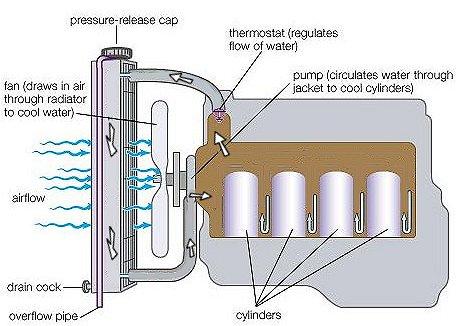
Liquid cooling is also employed in maritime vehicles. For
vessels, the seawater itself is mostly used for cooling. In some cases,
chemical coolants are also employed (in closed systems) or they are mixed with
seawater cooling. Water cooling is used in those engines where more cooling
effect is required. Most modern internal combustion engines are cooled by a closed circuit carrying liquid coolant through channels in the engine
block, where the coolant absorbs heat, to a heat exchanger or radiator where the coolant releases heat into
the air. Thus, while they are ultimately
cooled by air, because of the liquid-coolant circuit they are known as water-cooled
-AIR COOLED ENGINES

In all combustion engines, a great percentage of the heat generated (around 44%) escapes through the exhaust, not through either a liquid cooling system nor through the metal fins of an air-cooled engine (12%). About 8% of the heat energy finds its way into the oil, which although primarily meant for lubrication, also plays a role in heat dissipation via a cooler
-
Based on
type of ignition
1) Spark ignition engine
2) Compression ignition engine

-SPARK IGNITION ENGINE
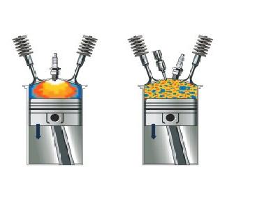
The term spark-ignition
engine normally refers to internal combustion engines, specifically petrol engines, where the initiation of the
combustion process of the air-fuel mixture is ignited within the combustion
chamber by a spark
from a spark plug. The term contrasts with
diesel-fueled compression-ignition
engines, where the
heat generated from compression is enough to initiate the combustion
process.
-COMPRESSION
IGNITION ENGINE

A diesel engine
(also known as a compression-ignition
engine and sometimes capitalized as Diesel engine) is an internal combustion engine that uses the heat
of compression to
initiate ignition to burn the fuel, which is injected into the combustion
chamber during the
final stage of compression. This is in contrast to spark-ignition engines such
as a petrol
engine (gasoline
engine) or gas engine (using a gaseous fuel as opposed to
gasoline), which uses a spark plug to ignite an air-fuel mixture. The diesel
engine is modeled on the Diesel cycle.
The diesel engine has the highest thermal
efficiency of any
regular internal or external
combustion engine
due to its very high compression ratio. Low-speed diesel engines (as used in
ships and other applications where overall engine weight is relatively
unimportant) often have a thermal efficiency which exceeds 50 percent.
-Based on fuel used
1) Petrol engines
2) Diesel engines
3) Gas engines
PETROL ENGINES

It differs from a diesel engine in the method of mixing the fuel and air, and in the fact that it uses spark plugs to initiate the combustion process. In a diesel engine, only air is compressed (and therefore heated), and the fuel is injected into the now very hot air at the end of the compression stroke, and self-ignites. In a petrol engine, the fuel and air are usually pre-mixed before compression (although some modern petrol engines now use cylinder-direct petrol injection).
The pre-mixing was formerly done in a carburetor, but now (except in the smallest engines) it is done by electronically controlled fuel injection. Petrol engines run at higher speeds than Diesels partially due to their lighter pistons, conrods & crankshaft (as a result of lower compression ratios) & due to petrol burning faster than diesel. However the lower compression ratios of a petrol engine gives a lower efficiency than a diesel engine.
DIESEL
ENGINES

A diesel engine (also known as a compression-ignition engine and
sometimes capitalized as Diesel engine)
is an internal combustion engine that uses the heat
of compression to
initiate ignition to burn the fuel, which is injected into the combustion
chamber during the
final stage of compression. This is in contrast to spark-ignition engines such
as a petrol
engine (gasoline
engine) or gas engine (using a gaseous fuel as opposed to
gasoline), which uses a spark plug to ignite an air-fuel mixture.
The fuel
injector ensures that the fuel is broken down into small droplets, and that the
fuel is distributed evenly. The heat of the compressed air vaporizes fuel from
the surface of the droplets. The vapour is then ignited by the heat from the
compressed air in the combustion chamber, the droplets continue to vaporize
from their surfaces and burn, getting smaller, until all the fuel in the droplets
has been burnt. The start of vaporization causes a delay period during
ignition, and the characteristic diesel knocking sound as the vapor reaches
ignition temperature and causes an abrupt increase in pressure above the
piston. The rapid expansion of combustion gases then drives the piston
downward, supplying power to the crankshaft. Engines for scale-model aero
planes use a variant of the Diesel principle but premix fuel and air via a carburetion
system external to the combustion chambers.

A gas engine means an engine running on
a gas, such as coal gas, producer gas biogas, landfill
gas, or natural gas. Generally the term gas engine
refers to a heavy duty, slow revving industrial engine capable of running
continuously at full output for periods approaching a high fraction of 8,760
hours per year, for many years, with indefinite lifetime, unlike say a gasoline
automobile engine which is lightweight, high revving and typically runs for no
more than 4,000 hours in its entire life. Typical power ranges from 10 kW
to 4,000 kW.
nice work piece, makes my assignment easier. THANKS
ReplyDeleteSir, Please tell about Knocking in Si and Ci engine
ReplyDeleteit is really nice information and very use full information for me
ReplyDeletemechanical